Course Guide
Smoke Trails
lesson 1
Getting Started
Start off by loading in your course geometry. You can easily access the provided geometry for the course by clicking the “ASSETS” button below any video in the course. In our case we are loading in missile and turret geometry for the smoke trails.
Core Objectives
Take our missile geometry, and set it up properly to simulate the missiles.
With our missiles simulated, it will form the basis for the trails that should emit from them.
Learn how to leverage particle simulations to do this.
Step 1: Separate Missiles and Turret Geometry
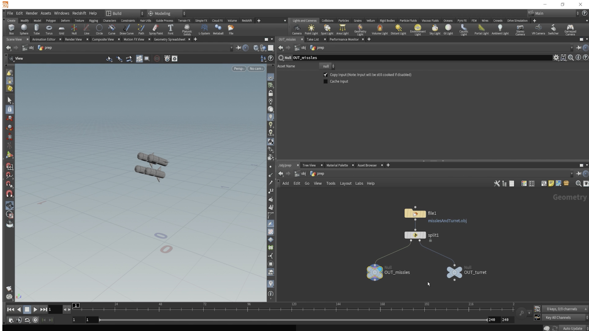

Split out your missiles and turret geo using a SPLIT node. The geometry have primitive groups on them for easy selection. Then designate one output with a NULL node and call it “OUT_turret”. Then call the other output “OUT_missiles”.
Next: Viewport Setup (Optional)
Rearrange your pan tabs to have a broader view of your viewport on the left and then your node graph on the right. You can always select a node, and hit “P” on the keyboard to access its given parameters.
Step 2: Reference Prepped Geo
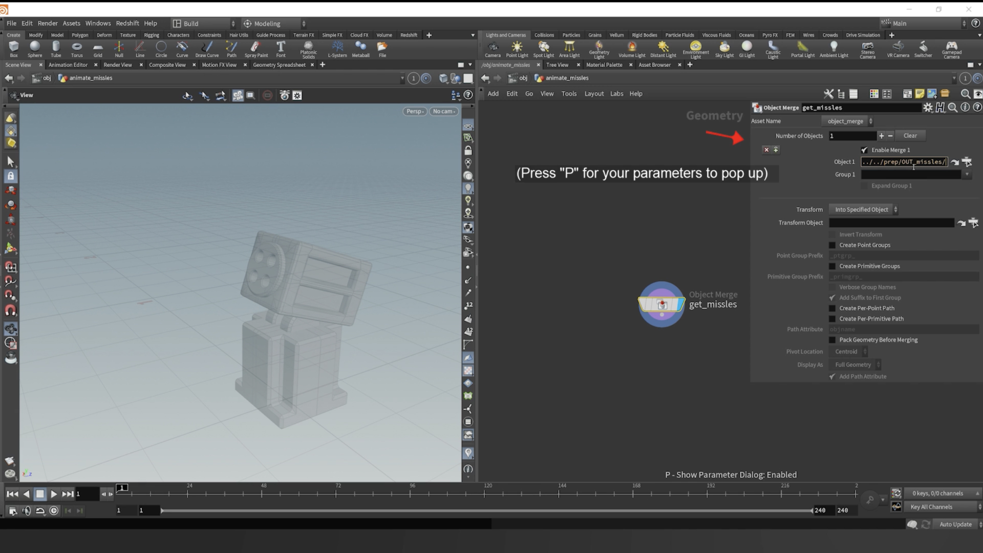

The Geometry SOP where you prepared the missile and turret split can be named “prep”. And now we can create another Geometry SOP in the OBJ context and call it “animate_missiles”. Jump inside the “animate_missiles” node, and import our “OUT_missiles” by using an OBJECT MERGE node.
What’s nice about Houdini, is it’s essentially organized like a folder system on your computer. You can reference paths to different geometries. In the OBJECT MERGE node, reference the “OUT_missiles” by typing: ”../../prep/OUT_missles”
Step 3: Create Name Attributes
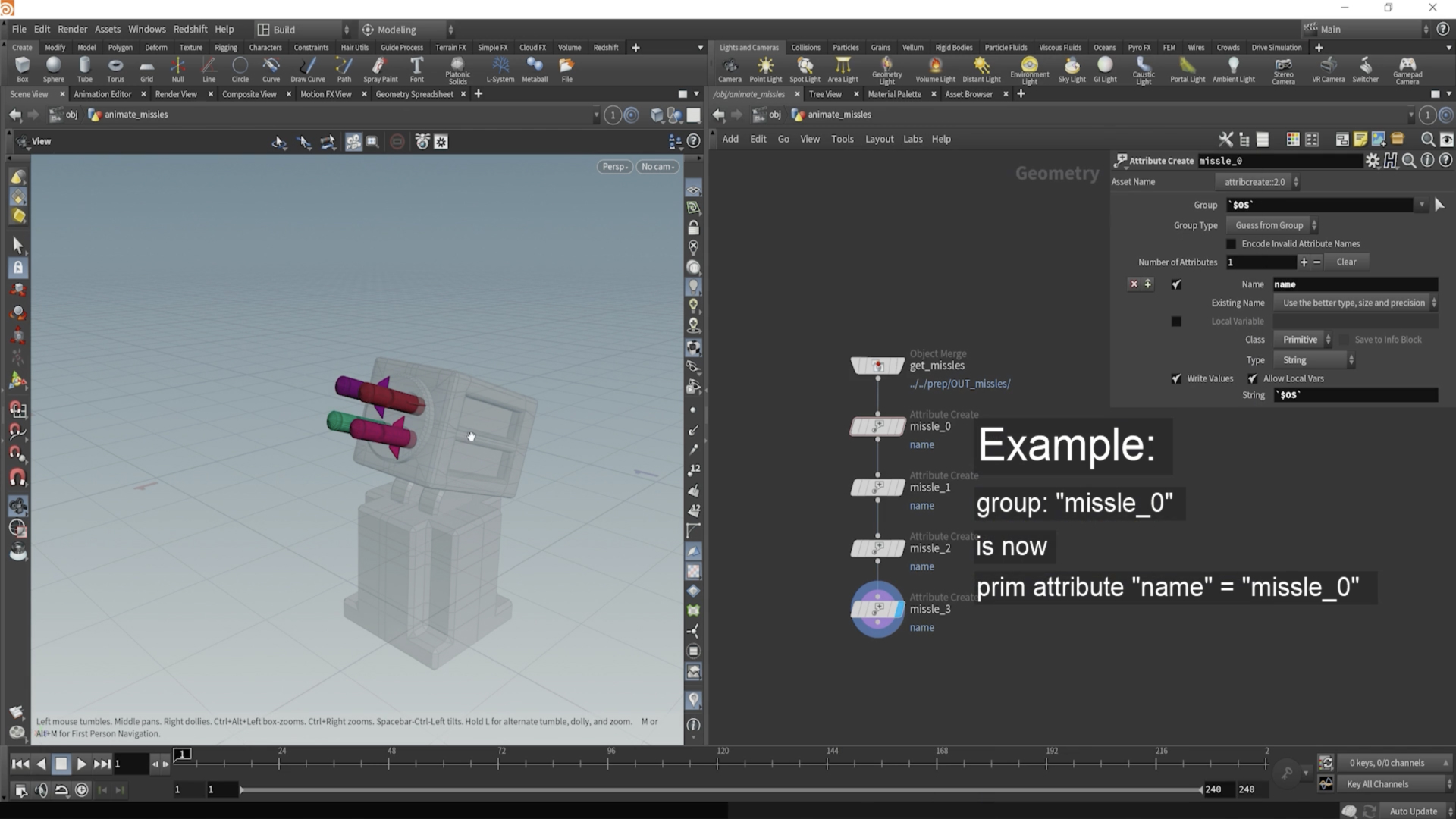

After object merging the missiles, let’s create a name attribute for each missile. We can do that by dropping down an ATTRIBUTE_CREATE node.
Make the Class = Primitive and make the Type = String
Then for the attribute name, you can type: (using back ticks, not apostrophes)
`$OS`
Then it will use whatever the name of the node is for the name of the attribute. For example, name the node “missile_01” and then the attribute will automatically update to being called “missile_01”.
Lastly make sure you select the appropriate group to be able to separate each missile.
Step 4: Turn Missiles into Packed Geometry
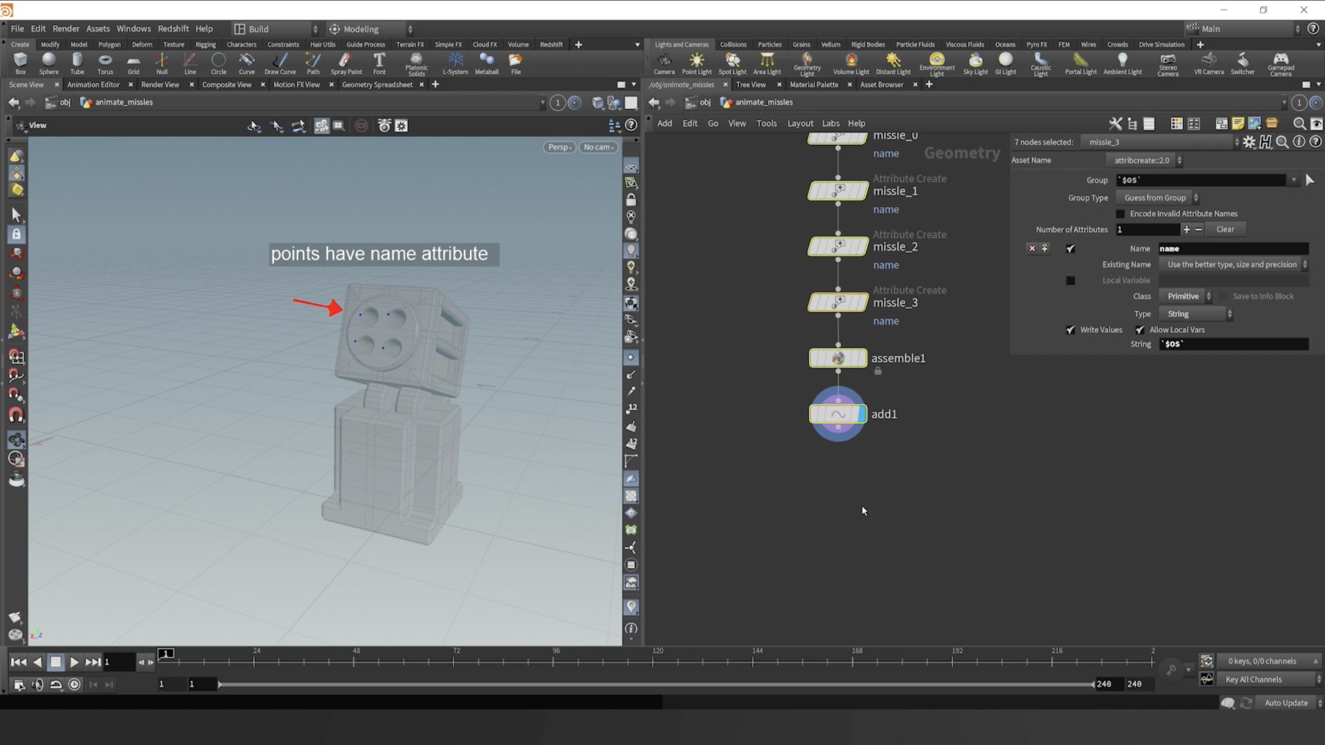

After doing that, you can drop down an ASSEMBLE node, and make sure to check “create packed geometry” and uncheck “create name”. This way we can pack each missile as an individual point representation — a packed point, with all its attributes.
Then we can simulate a single point and then copy the missile back onto each point later.
Drop down an ADD node, and check “delete geometry but keep points” and then pipe it into a POPNET node.
Step 5: Blast Points for Direction Attribute
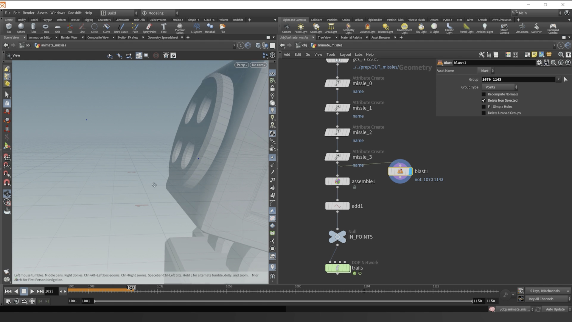

Next we need to create a direction that the missile points will shoot from as points in our simulation. In order to do that, on a forked path, you can drop down a BLAST node and then select the tip of a missile and then the bottom end of it, for two points total.
Step 6: VEX Code Direction V
Now that we have two specified points, we can utilize them to create a direction attribute called “v”. In Houdini, attributes that are written to the geometry are specified with a variable type, such as “v” for vector. In our case, we are additionally naming the vector “v”. This is potentially confusing, but it’ll start to make sense as we go further.
If we take the position of one point, and then subtract the position of the other point, it will create a new vector that points in the direction we want. All we need to do after that is normalize that direction so it’s unit length is equal to 1. This is standard when dealing with vectors that are treated as directions.
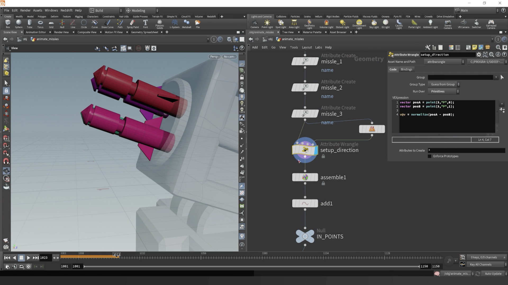
We want to drop down a PRIMITIVE_WRANGLE node after our last ATTRIBUTE_CREATE node and before the ASSEMBLE node. Then pipe in the blasted points into our 3rd input of the PRIMITIVE_WRANGLE. (It’s the 4th dot on top of the node, but Houdini orders the inputs starting with 0, so it’s actually specified as the 3rd input).
In the PRIMITIVE_WRANGLE, here’s the code we will need to put in:
Primitive Wrangle Code Snippet
Group Type:
Guess From Group
Run on:
Primitives
vector posA = point(3,"P",0);
vector posB = point(3,"P",1);
v@v = normalize(posA -
posB);

Step 7: Visualize our Direction V
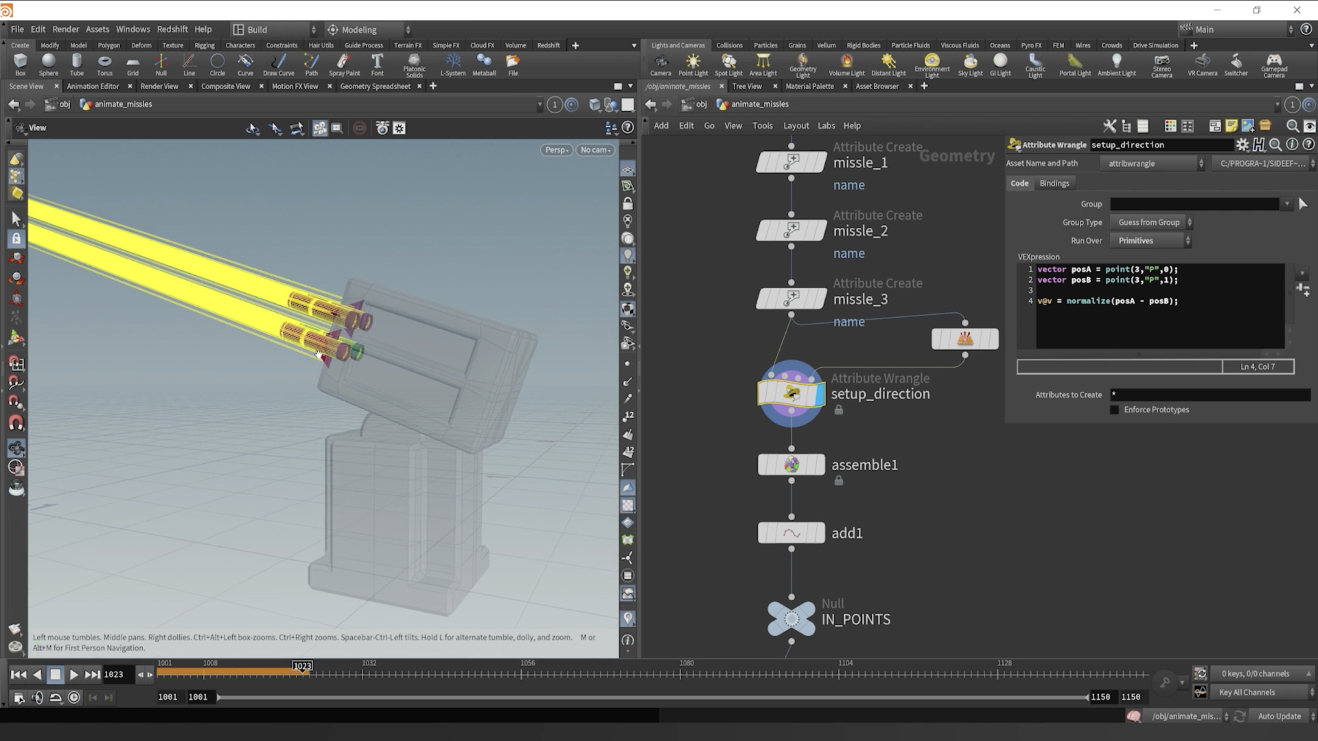

If we middle mouse click on our PRIMITIVE_WRANGLE node now, we should see a “v” attribute on the primitive level. If you click where it’s underlined, Houdini will create a visualizer for that given attribute. In our case, it recognizes it as a vector attribute, thus rendering yellow vectors in the viewport to show which direction the attribute is pointing.
Step 8: Promote the v attribute and sim prep
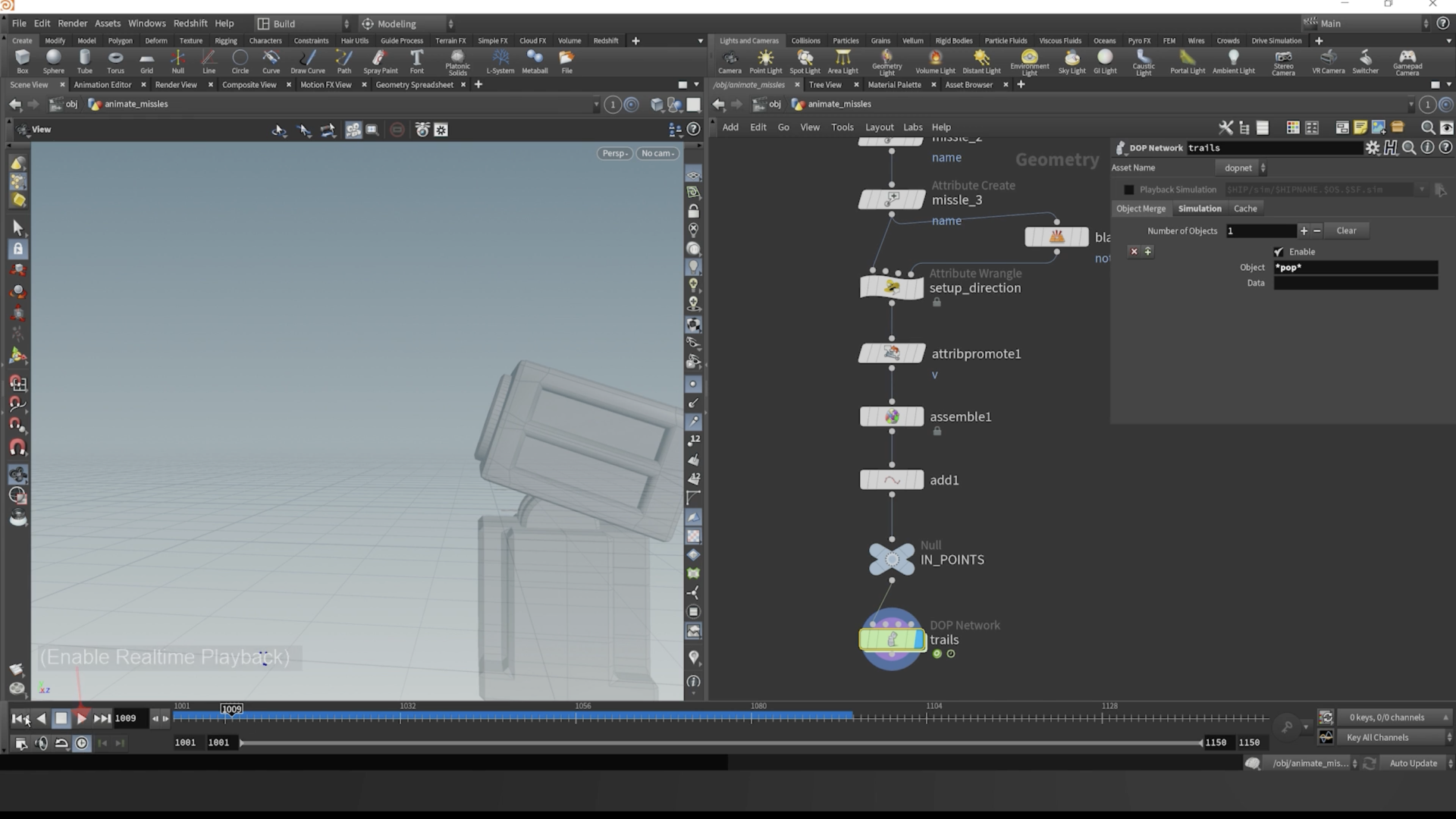

We need to promote our “v” attribute from the primitive level to the point level, in order to transfer them to our points when they are packed with the ASSEMBLE node. Drop down an ATTRIBUTE_PROMOTE node before the ASSEMBLE and you’ll change the primitive v attribute to a point v attribute.
Make sure to revisit the ASSEMBLE node and transfer “v” so the points will inherit that direction. “v” in Houdini is also reserved for point velocity. So if you have a vector attribute “v” on your points, and you pipe them into a POPNET simulation, Houdini will recognize that as the speed and direction for the points to go.
Lastly, make sure you click the POPNET node, and at the Object Merge tab, type *pop * in the Object parameter. This will make it so only the points are piped out of this simulation, as opposed to any other objects like collisions.
Step 9: Dive into POPNET and What's DOPS
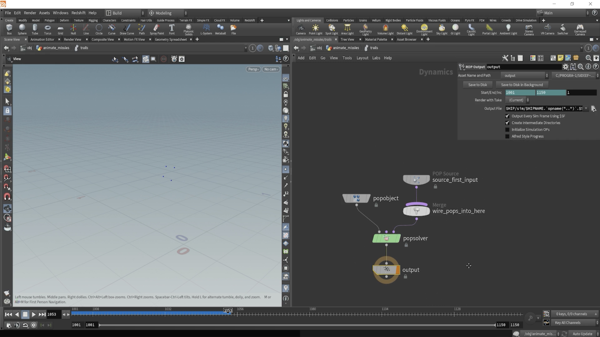

Now dive into our POPNET node, which brings us into a simulation environment in Houdini, known as DOPS. Nodes are different in DOPS, because they are set up to work with situations. When you hit Tab, to get nodes, you’ll notice they aren’t quite the same as they are in SOPS.
Our POP_SOURCE node in this network is going to control what is coming into our simulation. The POP_OBJECT node is the node that holds our point data throughout the simulation. The POPSOLVER runs the simulation calculations over all the points each frame.
And finally, the OUTPUT node is specified because that’s the node we want to reference outside of DOPS to extract our simulation data from DOPS.
Step 10: Simulation Specifics
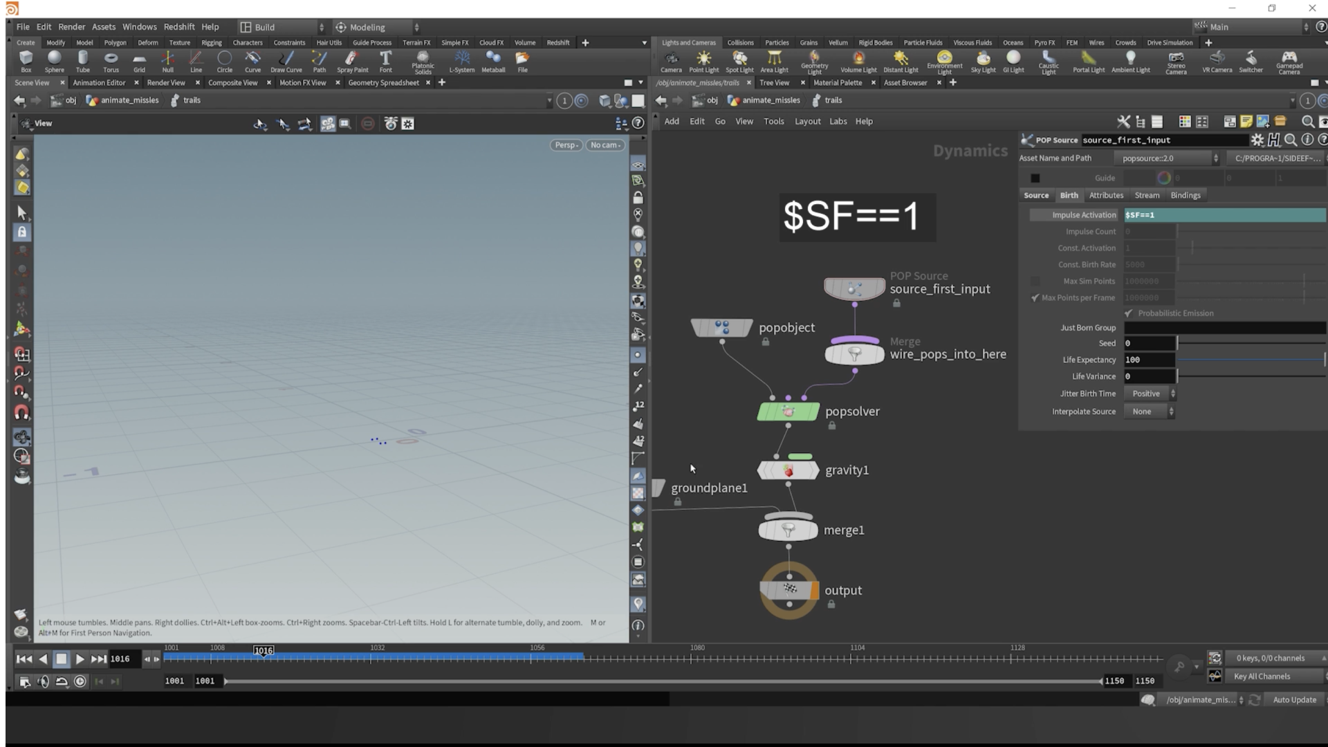

Next, drop down a GROUND_PLANE node, and pipe it into the left side of the MERGE node.
Order matters on merges in DOPS, unless you select the MERGE node and change the relationship behavior to “Mutual”.
For our purposes, we want to change the source of our simulation to “All Points” and then change the impulse activation to:
$SF==1
This will enable the sourcing to only occur at the first simulation frame. Hence SF. It means, “Simulation Frame”. So when the simulation frame is equal to 1, source the points.
Step 11: Collision Behavior
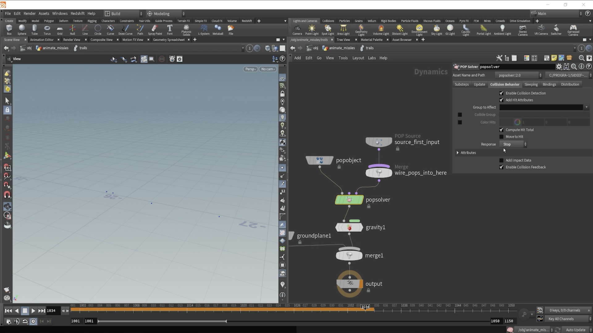

Click on the POPSOLVER node, and in the Collision Behavior tab, change the Response parameter to:
“Stop”
This will make it so the points stop once they hit the ground plane collision object.
Step 12: Pop Wrangle Vex
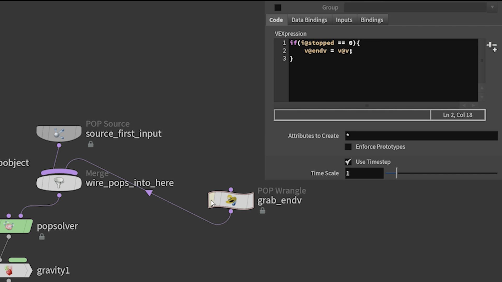
There’s a node in DOPS we can create called a POP_WRANGLE node. It’s essentially and ATTRIBUTE_WRANGLE, but for points inside of DOPS. Here’s we want to specify an attribute called “endv” and have it be a vector. This way we can record the direction in which each missile hits the ground when it stops.
Since we changed our Response in the Collision Behavior to “Stop”, we will have an integer attribute on our points called “stopped”. It is equal to 1 when the points collide, thus rendering them stopped.
Here’s the code we need to put in our POP_WRANGLE, and then pipe the wrangle into the last input of the MERGE node, with the POP_SOURCE node:
Pop Wrangle Code Snippet
Group Type:
Guess From Group
Run on:
Points
if(i@stopped==1){
v@v = v@endv;
}

Step 13: Update Simulation Velocity
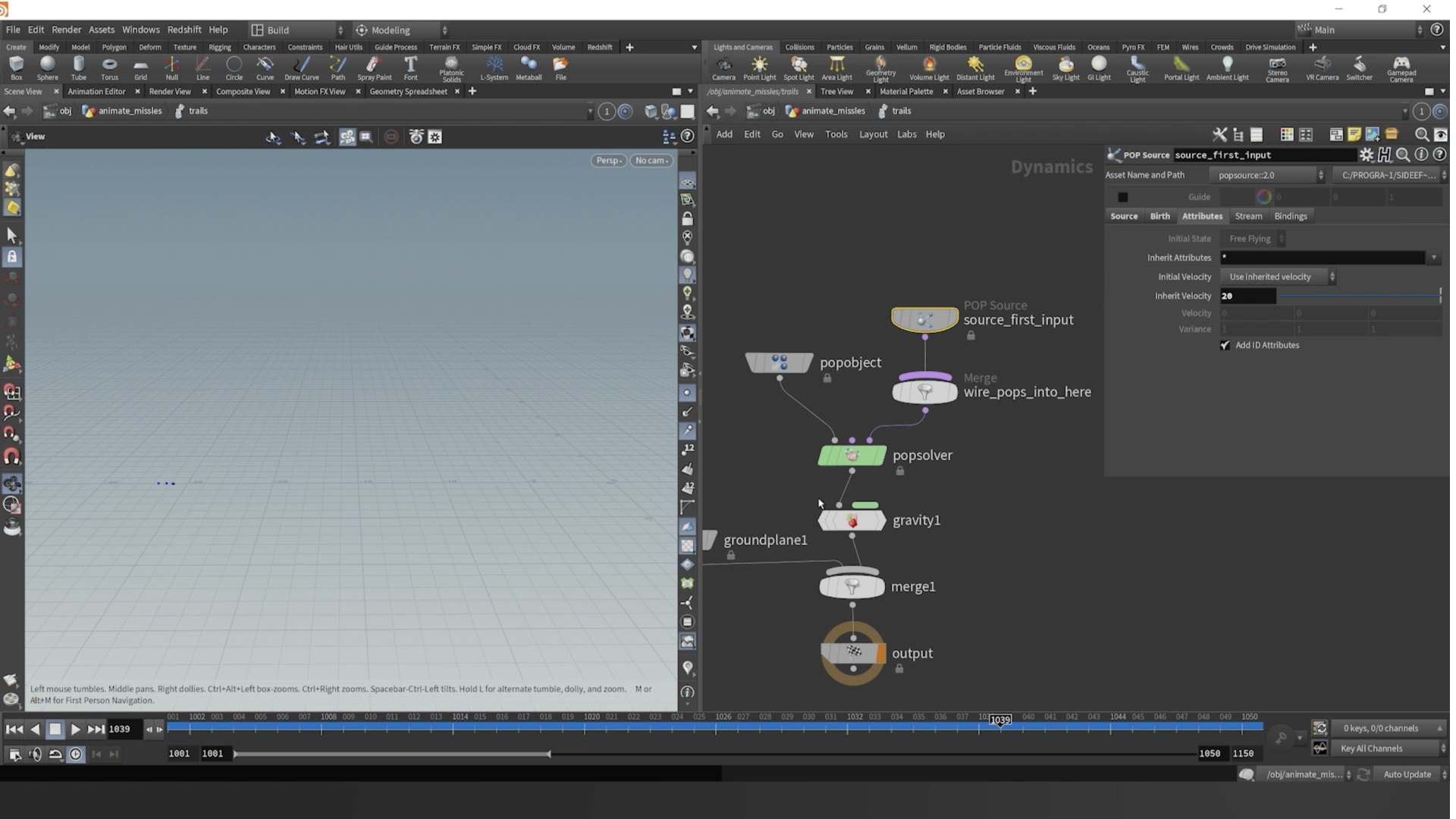

In the POP_SOURCE node, go to the Attributes tab and change the Inherit Velocity parameter to:
20
This way, our points inherit that velocity attribute we created, but the speed is now multiplied by 20, creating a nice arc.
Step 14: Wire Outputs After Simulation
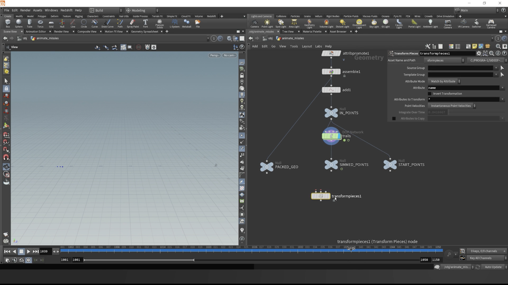

If we come out of our POPNET simulation node, we need to set up a way to have our missiles move according to where their corresponding point moved.
To do this, make a NULL node called “PACKED_GEO” and connect it to our ASSEMBLE node.
Then create another NULL node called “SIMMED_POINTS” and connect it to the output of our POPNET simulation.
And last, create a 3rd NULL node called “START_POINTS” and connect it to the output of the “IN_POINTS” NULL node.
Round this step off by creating a TRANSFORM_PIECES node.
Step 15: Set V to EndV Post Sim
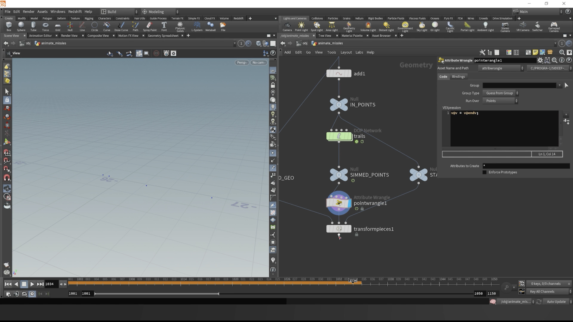
After the “SIMMED POINTS” node, we can create a point wrangle and set the v@v attribute to “v@endv”. This way, our points will land and hit the ground with the correct orientation.
Here’s the code for the POINT_WRANGLE node:
Point Wrangle Code Snippet
Group Type:
Guess From Group
Run on:
Points
v@v = v@endv;

Step 16: Final Step for the Lesson
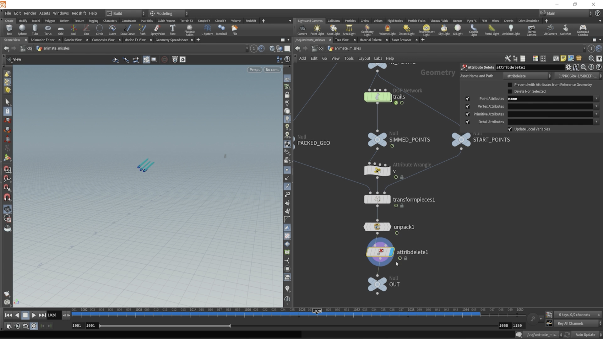

Our final step for the lesson will be to wire everything up correctly. Plug the “PACKED_GEO” node into the first input of our TRANSFORM_PIECES node. Hook the POINT_WRANGLE we just used to specify v with, into the 2nd input, and our last input will have our “START_POINTS” node plugged into it.
Since our packed geometry, and our simulation and start points all have matching name attributes, the TRANSFORM_PIECES node is able to deform our missile geometry correctly over each frame, thus have animated missiles.
Our last task is to drop down an UNPACK node, to unpack the missiles so they will act as normal animated geometry. And then drop down an ATTRIBUTE_DELETE node and delete the name attribute at just the point level, NOT the primitive level. This will make things easier for further lessons, because our attributes will be set up correctly.